Hi ,
I always use github but I never shared my repositories.
My repositories:
– burglar alarm system
– timer
Bests,
Giuseppe
Hi ,
I always use github but I never shared my repositories.
My repositories:
– burglar alarm system
– timer
Bests,
Giuseppe
Here I am again with the timer.
As I explained in the previous post I want to turn on and/or turn off an electrical appliance at 220 V using relays.
I never had any experience in using relays, then at the moment the scheme will include a led.
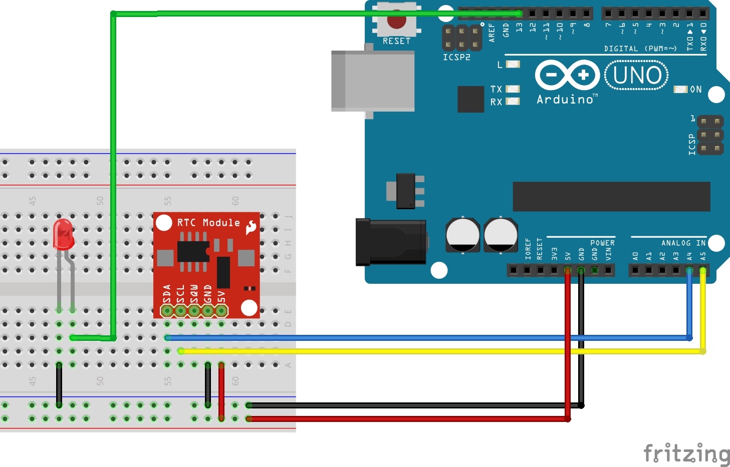
Here is the schema seen previously with the addition of led connected to PIN 13 Arduino digital:
And here is the code:
#include <Wire.h>
#include <String.h>
#include "RTClib.h"

#define BUFFER_SIZE 20
#define STATE_OFF  0
#define STATE_ON   1

//Giornate di programmazione
const int numeroProgrammazioni = 4;
String Monday[numeroProgrammazioni] = {
  "21:35", "20:30","20:35","20:40"};
String Tuesday[numeroProgrammazioni] = {
  "11:00", "11:35","13:10","13:50"};
String Wednesday[numeroProgrammazioni] = {
  "20:55", "19:58","20:00","20:05"};
String Thursday[numeroProgrammazioni] = {
  "10:00", "10:35","17:10","20:00"};
String Friday[numeroProgrammazioni] = {
  "10:00", "10:35","14:10","15:00"};
String Saturday[numeroProgrammazioni] = {
  "18:15", "18:20","18:22","18:25"};
String Sunday[numeroProgrammazioni] = {
  "10:00", "10:35","12:10","15:00"};
//Fine giornate di programmazione

RTC_DS1307 rtc;
int fsm_state;
String START_TIME;
String END_TIME;
int nSize = numeroProgrammazioni / 2;
String giornoTemp[numeroProgrammazioni];

void setup () {
  //Serial.println("Inizio Setup");
  fsm_state = STATE_OFF;
  Serial.begin(57600);
#ifdef AVR
  Wire.begin();
#else
  Wire1.begin(); // Shield I2C pins connect to alt I2C bus on Arduino Due
#endif
  rtc.begin();

  if (! rtc.isrunning()) {
    rtc.adjust(DateTime(F(__DATE__), F(__TIME__)));
  }

  pinMode(13,OUTPUT);        //Collegamento al LED
}

void loop () {
    // Ricavo il time attuale
    DateTime now = rtc.now();

    int giorno = now.dayOfWeek();      //0 = Monday 1 = Tuesday 2 = Wednesday ....
    //Serial.println( giorno);
    if (giorno == 1){                  //Monday
      memcpy(giornoTemp,Monday, sizeof(Monday));
    }
    else if (giorno == 2){            //Tuesday
      memcpy(giornoTemp,Tuesday, sizeof(Tuesday));
    }
    else if (giorno == 3){            //Wednesday
      memcpy(giornoTemp,Wednesday, sizeof(Wednesday));
    }
    else if (giorno == 4){            //Thursday
      memcpy(giornoTemp,Thursday, sizeof(Thursday));
    }
    else if (giorno == 5){            //Friday
      memcpy(giornoTemp,Friday, sizeof(Friday));
    }
    else if (giorno == 6){            //Saturday
      memcpy(giornoTemp,Saturday, sizeof(Saturday));
    }
    else if (giorno == 7){            //Sunday
      memcpy(giornoTemp,Sunday, sizeof(Sunday));
    }

    //verifico lo stato che dovrà assumere
    int isON = 0;
    for (int i= 0; i< nSize;i++){
      START_TIME = giornoTemp[i*2];
      END_TIME = giornoTemp[(i*2)+1];
      isON = setStatus(now,START_TIME,END_TIME);
      gestisciCarico(isON);
    } //end for

  delay(3000);
}

int setStatus(DateTime timeOra, String START_TIME, String END_TIME)
{
  //recupero l'ora
  DateTime dSTART_TIME = DateTime(timeOra.year(),timeOra.month(),timeOra.day(),START_TIME.substring(0, 2).toInt(),START_TIME.substring(3, 5).toInt(),0);
  DateTime dEND_TIME = DateTime(timeOra.year(),timeOra.month(),timeOra.day(),END_TIME.substring(0, 2).toInt(),END_TIME.substring(3, 5).toInt(),0);
  long lSTART_TIME = dSTART_TIME.unixtime();
  long lEND_TIME = dEND_TIME.unixtime();

  switch(fsm_state) {
  case STATE_OFF:
    if(timeOra.unixtime() > lSTART_TIME && timeOra.unixtime() < lEND_TIME) {
      fsm_state = STATE_ON;
      //Serial.println("caso 1");
    }
    break;
  case STATE_ON:
    if(timeOra.unixtime() > lEND_TIME) {
      fsm_state = STATE_OFF;
      //Serial.println("caso 2");
    }
    break;
  }

  return fsm_state;
}

void gestisciCarico(int isON)
{
  if (isON == 1){
    digitalWrite(13,HIGH);
  }
  else
  {
    digitalWrite(13,LOW);
  }
}
Code explanation:
from line 12 to line 25: setting times of day when turn led
row 47: setting RTC with time and date code compilation
row 50: setting led connection on pin 13
In the loop:
row 55: updating RTC with current day and time
row 57: Getting current day (0= monday, 1 = thusday…).
In this way i can undestand which array I have to use to determine hour settings.
line 86: using the setStatus function to test whether or not turn on the led
row 84: function setStatus: to compare dates using the function unixtime () that converts the date to unix (long): The function returns an int (0/1) 1 turn on led and 0 turn off
line 87: gestisciCarico function: the function takes as input the value previously returned. At this point it is actually switched on led.
This is actually what we wanted: our led will turn on or off in the hours established by us.
The next steps, which I’ll explain soon are:
1. adding a random function (optional): If the random function is activated, I’ll add some random minutes to the hour I decided in array.
2. using relay to turb off or on a 220v bulb.
That’s all.
Happy 2016!
Hello again everyone, thanks to my dad’s suggestion, I’d like to use Arduino to turn on and turn off a lamp or any 220 V device at certain times of the week.
So for example:
-on Monday I want my lamp lights at 8.15 till 9.40, in the afternoon from 17.10 at 17.45.
-on Tuesday, at 9.20 a.m. 10.50 a.m.
-on Wednesdays from 10.00 a.m. to 11.00 a.m. and in the afternoon from 15.10 at 15.45
and so on, until Sunday
To do this I got the chip DS1307:it’s a very cheap RTC (real-time clock) that allows you to keep track of time and date.
It also has a buffer battery which ensures the functioning of the internal clock in the absence of external power.
It is possible to communicate with the chip via I2C Protocol, so we can use the Wire library.
The connection between arduino and the chip is very simple, as shown in the picture below:
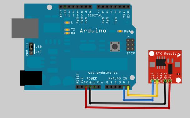
To summarize:
| Arduino Pin | PIN DS1307 |
| 5 V | 5 V |
| GND | GND |
| Analog pin 4 | SDA |
| Analog pin 5 | SCL |
Connections between Arduino and the chip will vary depending on the model of Arduino (Uno, leonardo, etc).
In fact the PIN SDA (data line) and SCL (clock line) differ above:
| Board | I2C/TWI pins |
| Uno, Ethernet | A4 (SDA), A5 (SCL) |
| Mega2560 | 20 (SDA), 21 (SCL) |
| Leonardo | 2 (SDA), 3 (SCL) |
| Due | 20 (SDA), 21 (SCL), SDA1, SCL1 |
In the next post we will see how to handle date and time, and how you can use this information when we want to turn on a device.
Bye!!!
For my latest experiments (see previous post) I decided to buy my first Arduino clone.
Once written the sketch I tried to upload it: nothing, no USB communication with my MAC system.
Reading the ad and looking better the tab, I found that the chip that is responsible for the serial communication is not present in the original Arduino boards but is the CH340G chip (USB/Serial Interface).
It is therefore necessary to find the correct drivers to handle the chip.
I found this very interesting guide searching in Internet.
Summary for my future and memory for those who follow me:
sudo nvram boot-args="kext-dev-mode=1"
At this point in the Arduino Ide, on the Tools menu, serial port, you can select the correct serial port.
I hope you can help!
Buongiorno a tutti,
mi presento, sono Giuseppe.
Sono un programmatore NET con la passione per la corsa, la bicicletta e per lo sport in generale.
Ed ora di Arduino: ho scoperto un mondo nuovo, di passione e di fantasia.
Sono completamente nuovo in questo mondo, ma voglio provarci e scrivere dei miei “successi” e dei miei fallimenti.
Spero di avere suggerimenti e perché no, critiche, in modo da poter migliorare ed imparare.

Giuseppe